Case study
Where the codes fall down
The various codes and guidelines ensure that heat exchangers are safe to operate. The mechanical integrity of the plates, tubes, shells and flanges is assured by compliance with the design criteria. This does not ensure that leaks will not occur (as they often do).
The first weak point is the flange design, particularly for girth flanges. Design engineers use the criteria to provide the least costly solution (it's a very competitive business), which mostly results in the smallest and thinnest flanges. One way to optimize this is to use high multiples of small diameter bolts.
This complies with code but creates a maintenance nightmare. The interaction between each bolt during the tightening assembly process causes very high variations in residual bolt tension. The bolt tightening industry generally states that torque tightening is +/- 25% accurate but, with high interactions, this figure is often +25%-100% (it's very common to find at least one bolt loose after the final tightening sequence).
The available bolt tightening methods
This effect can be minimised, or even eliminated, by use of multi-point bolt tightening systems, such as Hydraulic Bolt Tensioners, if they’re available and suitable (which they often aren't).
To explain the last comment, when codes and manufacturers are combined, they fail to provide a solution. The TEMA bolt spacing and weld neck taper mean that only a small tensioner will fit. As the piston size determines the applied tension, and this is governed by the available space, wherever a tensioner is used, the pre-load that it can apply is very low. The manufacturers also rarely sell small tensioners, as the industry perception is that "small bolts don't need to be hydraulically tensioned".
Another restriction to the use of bolt tensioners is, that due to the multitude of dimensions that TEMA allows it is unlikely that a range of sizes can be harmonised.
The second method is controlled bolt torquing. Each bolt is tightened in a start pattern at 30% of the assumed torque, then at 60%, then 100% and then, again, at 100%. It is a slow process and, as our results show, highly inaccurate.
Manufacturers offer multi (four) point options but this has no effect on the inaccuracy, nor is it any quicker. Most field technicians are convinced that single point is much faster, the pump unit runs extremely slowly when its trying to charge four outlets.
Manufacturing methods
Reputation is extremely important to manufacturers: the quality is rarely in question and all fabricators strive to do a good job.
It is a requirement that stringent inspection points are completed by the manufacturers and, in many cases, an independent inspector will be required to witness and verify those inspections. The issue here is that the codes do not state at what stage in the manufacturing process these must be completed.
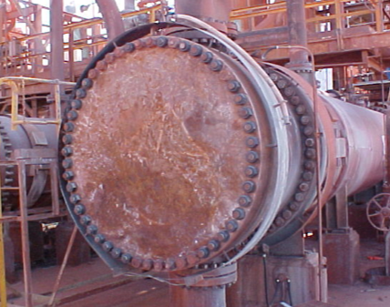
Common Heat Exchanger Bolt Pattern, several small bolts, high bolt load interaction losses, high inaccuracy, often difficult to fit hydraulic bolt tensioners of adequate capacity.
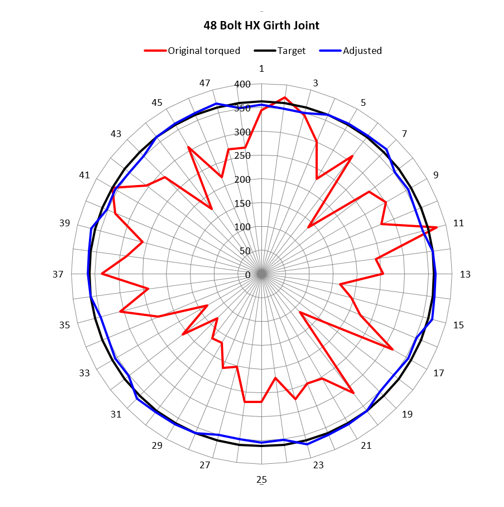
Results from ultrasonic bolt tension measurements. Original results adjusted to provide even force and leak free joint. The original tightening occurred in the standard “star pattern” four (4) pass (30%, 60%, 100% and 100% of calculated torque setting).
The Solutions
Codes
A clear understanding of what the codes allow can help the client to upgrade the specifications for a better long term solution. For instance, a simple statement of a maximum number of bolts on a large girth flange (> 1m) is 24, or that all bolts must be a minimum of 1 1/4in diameter. This will force each designer to increase the thickness and diameter.
Another could be "flanges to be designed to fit hydraulic bolt tensioners and retain a bolt tension must not be less than 50% of yield stress". Some manufacturers in South Korea have adopted this process. The Bolt Tensioner manufacturer also worked on reducing the tool size in order to minimise the dimensional increase of the flange.
The Bolt load design specification placed in the HX purchase order could specify:
-
That flange sealing bolts must target 50% yield stress as the operating condition, this ensure preload bolting devices do not overload the bolt with the applied load. It also ensure more bolts and
-
That bolt assembly spot faces machined surface diameter is 5 times the designed bolt diameter, this will ensure bolt tensioning devices will fit the flange adequately.
-
That QA documents of bolt load, bolt applied load and gasket type and dimensions are a Purchase Order quality deliverable and performance warranty item.
Example
Changing from 60 x 1in to 2in bolts can reduce the number from 60 down to 16, which is both much quicker and improves accuracy significantly.
This example would result in flanges having a 5-10% thickness increase and a 10-20% increase in the outside diameter.
Bolt tightening methods
In the case where the heat exchanger is an existing unit that cannot easily be modified measured, control methods will resolve the failures.
To do this, there are several methods: ultrasonic bolt stress monitoring, compression load cells, strain gauges, gauge rod bolts etc. All of these work and used the same basic procedures:
-
Measure the tension of each bolt
-
Identify the lows
-
Adjust the low ones to the target
-
Re-measure each bolt; normally the highs will relax slightly after this
-
Adjust the new lows to the target
-
This will provide a joint with even bolt tension that will not leak.
BP Oil, Total, Agip, EDF, Endessa, National Power, and Shell at several refineries and power stations have successfully employed this latter method.
Manufacturing Methods
The two inspections that should be carried out at specific times are the flange sealing faces and the tube sheet sealing surface and division plate grooves.
Tube sheets will either have the heater tubes welded or expanded to them. This will, inevitably, cause distortion. In most cases, the inspection of the sealing surfaces will occur prior to this activity. Consequently, records will show that the items are compliant but in practice, they will not be.
Girth flange sealing surfaces are machined, compliant and verified before they are welded to the shell and the channel cover. This will cause distortion and it is likely that the sealing surfaces will not be compliant.
The solution is that the final machining should happen after the welding and tube expansion processes. In the case where it’s an existing unit, there are many capable in-situ machining providers who can do this work on site.
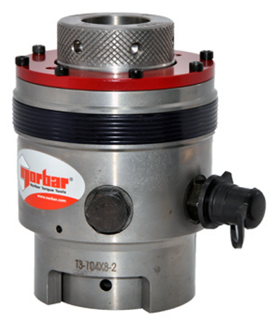
Typical Hydraulic Tensioner assembly
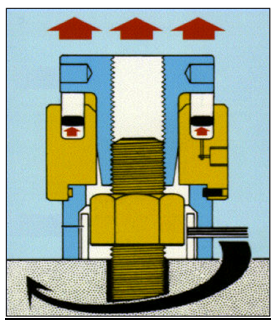
Sectional View of a Hydraulic Bolt Tensioner, pressure x piston area = force applied
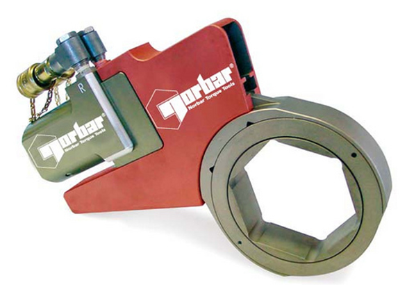
Cassette Style Hydraulic Torque Wrench, in comparison to square drive types it is safer, quicker ad induces less bending.
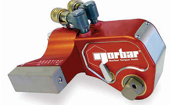
Square Drive Hydraulic Torque Wrench, very flexible as many different socket sizes can be applied. Lowest cost but highest inaccuracy.